 Royal Enfield Interceptor 650 - Service manual > Engine Assembly to Frame
Engine Assembly into Main Frame

Cradle Frame Assembly into Engine

Engine Mounting Bolts

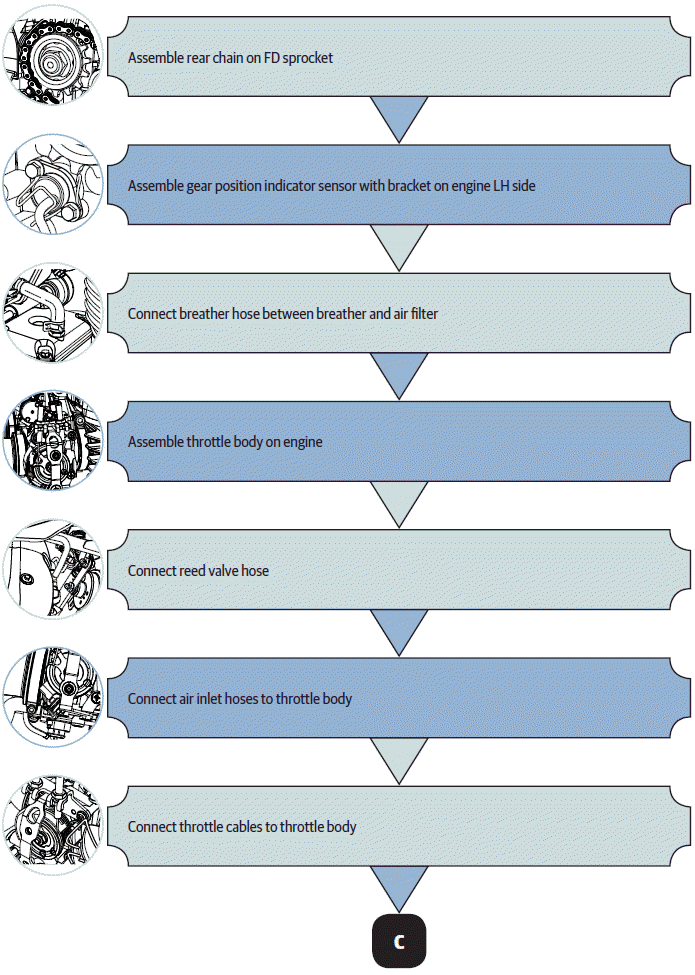
COMPONENTS ASSEMBLY SEQUENCE TO ASSEMBLE ENGINE INTO FRAME - FLOW CHART


- Cradle Assembly RH
- Engine Cylinder Head Steady Bracket
- Breather Hose Connection
- Silencer RH on Exhaust Pipe
- Fuel Tank
- Oil Cooler Inlet and Outlet Pipes
See also:
 Royal Enfield Interceptor 650 - Service manual > Cradle Frame Top Mountings
Cradle Frame Top Mountings from Main Frame Support engine/cradle frame with scissor jack (a) so that it will not fall off when mounting bolts are removed. Loosen and remove 2 Nos. Hex socket head bolts (M10) (a) on LH and RH holding cradle frame top (b) on main frame (c).
 Royal Enfield Interceptor 650 - Service manual > Cradle Assembly RH
WARNING DO NOT tighten bolts during initial installation. Support engine suitably and firmly on a work table and ensure it is stable. Locate cradle frame RH (a) on engine RH side (b). Align mounting holes (a) of cradle frame with mounting holes on engine. Insert Hex head bolt long (M10) (a) with washer (c) into mounting holes on cradle frame RH top (b). DO NOT TIGHTEN FULLY. Insert Hex head bolt small (M10) (a) into mounting holes on cradle frame RH (b) bottom. Assemble washer and nut (c) on bolt. DO NOT TIGHTEN FULLY.
 Rider's Manual BMW R 1250 GS GSA
 Owner's Manual Harley-Davidson Sportster XL1200X Forty-Eight
 Owner's Manual Honda CBR650R
 Service manual Honda CBR650
 Owner's Manual Honda PCX125
 Owner's Manual Kawasaki Z1000SX
 Service manual Kawasaki Z1000SX
 Owner's Manual Lexmoto Echo
 Owner's Manual Royal Enfield Interceptor 650
 Service manual Royal Enfield Interceptor 650
 Owner's Manual Yamaha MT-07