 Royal Enfield Interceptor 650 - Service manual > Cradle Frame Top Mountings
Cradle Frame Top Mountings from Main Frame
- Support engine/cradle frame with scissor jack (a) so that it will not fall off when mounting bolts are removed.

- Loosen and remove 2 Nos. Hex socket head bolts (M10) (a) on LH and RH holding cradle frame top (b) on main frame (c).

Cradle Frame Bottom Mountings
Cradle Frame Bottom Mounting LH and RH from Main Frame
- Locate and loosen 2 Nos. Hex socket head (M10) (a) on LH and RH cradle frame bottom (b) mounted on main frame (c).

Rear Top Engine Mountings
Rear Top Engine Mounting from Main Frame
- Loosen and remove Hex nut (M10) (a) along with washer from RH top mainframe (b).

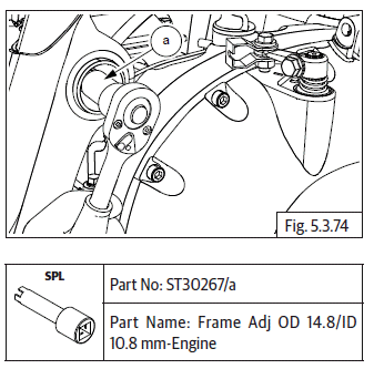
- Locate special tool (a) on main frame to loosen top mounting adjuster from frame RH on rear side of engine.

- Remove Hex nut (M10) (a) and washer from rear lower bottom of engine RH OR clutch cover (b).

- Locate special tool (a) on rear RH lower bottom of engine to remove adjuster from frame RH.

- Remove long bolt (M10) (a) from LH side of the engine (b).

Engine from Main Frame
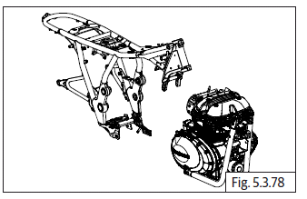
Lower Bottom Support and Slide Out Engine along with Cradle Frame from Main Frame
- Ensure bottom of engine is supported suitably.
- Gently lower engine with cradle frame from main frame.

Mounting Studs of Engine to Cradle Frame
Four Mounting Studs of Engine to Cradle Frame
- Support the engine suitably.
- Loosen and remove Hex flange head bolt (M10) (a) along with nut (M10) (b) and washers (c) from LH lower bottom of engine.

- Loosen and remove Hex flange head bolt (M10) (a) along with washer (c) from LH front top of engine to cradle frame (b).

- Remove Hex head bolt (M10) (a) along with nut and washers (b) from engine front top mounting to cradle frame LH.

- Loosen and remove Hex flange head bolt (M10) (a) along with nut (M10) (b) and washers (c) from LH lower bottom of engine.

- Separate cradle frames (a) from engine (b) and keep it in storage bin.

See also:
 Royal Enfield Interceptor 650 - Service manual > Magneto/Gear Position/Side Stand
Magneto/Gear Position/Side Stand Switch Couplers Connections Disconnect the gear position sensor (a) located on rear side of engine (b). Disconnect magneto sensor connector (a) located on rear side of engine (b). Disconnect side stand switch connector (a) located on rear bottom of engine (b). Disconnect crank position sensor connector (c).
 Royal Enfield Interceptor 650 - Service manual > Engine Assembly to Frame
Engine Assembly into Main Frame Cradle Frame Assembly into Engine
 Rider's Manual BMW R 1250 GS GSA
 Owner's Manual Harley-Davidson Sportster XL1200X Forty-Eight
 Owner's Manual Honda CBR650R
 Service manual Honda CBR650
 Owner's Manual Honda PCX125
 Owner's Manual Kawasaki Z1000SX
 Service manual Kawasaki Z1000SX
 Owner's Manual Lexmoto Echo
 Owner's Manual Royal Enfield Interceptor 650
 Service manual Royal Enfield Interceptor 650
 Owner's Manual Yamaha MT-07