 Royal Enfield Interceptor 650 - Service manual > Engine Removal from Main Frame
Engine Removal from Main Frame

Cradle Frame Removal from Engine

Engine Mounting Bolts

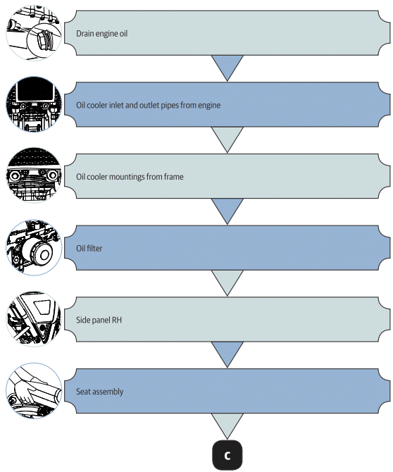
Components dismantling sequence to remove engine from frame - flow chart


WARNING The engine and exhaust system get extremely hot during normal operation and direct contact with skin can cause serious burns. Make sure engine is in normal temperature (OR) cooled before starting operation.
- Engine Oil
- Fuel Pump Connector and Fuel Level Sensor
- Magneto/Gear Position/Side Stand
- Cradle Frame Top Mountings
See also:
 Royal Enfield Interceptor 650 - Service manual > Magneto Cover Sub Assembly
Stator coil with CPS in magneto cover Position stator coil (a) inside magneto cover such that The crank position sensor (CPS) is seated at its mounting location. Magneto wires and grommet are aligned to the slot on the top of the cover. The stator mounting holes are aligned to the mounting holes in magneto cover. Locate 3 Nos. Hex socket head bolts (M6) (b) in the stator coil mounting holes and tighten evenly to specified torque. Locate guide plate (b) over the CPS (a), ensure the mounting holes of the guide plate, CPS are aligned to the mounting holes in magneto cover. Locate 2 Nos. Hex socket head screws (M5) (c) on the guide plate and tighten evenly to specified torque.
 Royal Enfield Interceptor 650 - Service manual > Engine Oil
NOTE Ensure the motorcycle is placed on a firm flat surface, resting it on the center stand/ramp. Before starting the dismantling process, start the engine and let the engine warm up for a few minutes and then turn it OFF. Remove engine oil filler cap (a). Place a tray (a) under engine oil magnetic drain plug (M14) (b). Remove it along with washer (c) to drain oil completely from engine.
 Rider's Manual BMW R 1250 GS GSA
 Owner's Manual Harley-Davidson Sportster XL1200X Forty-Eight
 Owner's Manual Honda CBR650R
 Service manual Honda CBR650
 Owner's Manual Honda PCX125
 Owner's Manual Kawasaki Z1000SX
 Service manual Kawasaki Z1000SX
 Owner's Manual Lexmoto Echo
 Owner's Manual Royal Enfield Interceptor 650
 Service manual Royal Enfield Interceptor 650
 Owner's Manual Yamaha MT-07