 Royal Enfield Interceptor 650 - Service manual > Horn Dismantling/Assembly
Electrical System / Horn Dismantling/Assembly
Horn Dismantling
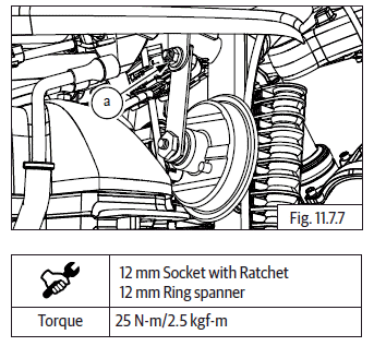
- Disconnect the RH horn connectors (a).

- Disconnect the LH horn connectors (a).

- Loosen and remove Hex flange bolt and nut (M8) (a) to remove RH horn bracket.

- Loosen and remove Hex flange bolt and nut (M8) (a) to remove LH horn bracket.

Inspection
- Inspect connector pins for any bends, corrosions and damages.
- Inspect headlamp holder for any scratches, rust, cracks and damages. Replace if it is defective.
- Inspect and replace reflector if it has any damages and/or distraction.
- Inspect if wire clips are loosened and tighten appropriately.
- Inspect if headlamp holder bolt is loosened and tighten appropriately.
- Inspect the bulb filament for any damages and replace.

Battery
- Check battery for any damages.
- Check the battery terminals for sulfating, corrosion or damages.
- Test voltage level. It should be 12.8V to 13.2V approximately.

Horn Assembly
- Locate and tighten Hex flange bolt and nut (M8) (a) into RH horn bracket.

- Locate and tighten Hex flange bolt and nut (M8) (a) into LH horn bracket.

- Connect the LH horn connectors (a).

- Connect the RH horn connectors (a).

See also:
 Royal Enfield Interceptor 650 - Service manual > Battery Dismantling
Battery Terminals Remove the following parts: Side panel RH. Rider seat. Side panel LH. Ensure Ignition and stop switch are in OFF position before disconnecting battery cables. Refer general information for battery connection and disconnection procedure.
 Royal Enfield Interceptor 650 - Service manual > Battery Assembly
RR Unit Locate RR unit (a) into engine guide rear along with bracket and gently slide up to fix RR unit. Insert and tighten 2 Nos. Hex flanged bolts (M6) (a) along with washer to fix RR unit. Connect RR unit connectors (a) and (b) into wiring harness and ensure they are locked properly.
 Rider's Manual BMW R 1250 GS GSA
 Owner's Manual Harley-Davidson Sportster XL1200X Forty-Eight
 Owner's Manual Honda CBR650R
 Service manual Honda CBR650
 Owner's Manual Honda PCX125
 Owner's Manual Kawasaki Z1000SX
 Service manual Kawasaki Z1000SX
 Owner's Manual Lexmoto Echo
 Owner's Manual Royal Enfield Interceptor 650
 Service manual Royal Enfield Interceptor 650
 Owner's Manual Yamaha MT-07