 Royal Enfield Interceptor 650 - Service manual > Gear Shifter Shaft
Engine / Components Removal from Engine / Gear Shifter Shaft
- Remove the circlip (a) from shifter shaft (b) on engine LH side.

- Remove the washer (a) from shifter shaft.

- Gently pull out shifter shaft assembly (a) from engine RH side.

- Remove circlip (a) from shorter end of shifter shaft (b).

- Remove washer (a) from shorter end of shifter shaft (b).

- Remove spring (a) from shifter shaft (b).

- Remove plate (a) from shorter end of shifter shaft (b).

- Remove circlip (a) from longer end of shifter shaft (b).

- Remove washer (a) from longer end of shifter shaft (b).

- Expand spring lugs and pull out spring (a) from longer end of shifter shaft (b).

Stator and GPS Wiring Connectors
NOTE
- Ensure 2 Nos. black wiring connectors located on rear side of engine are disconnected.

FD Sprocket Cover
- Loosen and remove 3 Nos. Hex socket head screws (M6) (a) from FD sprocket cover (b) on the LH side of engine, in the order shown (1, 2 & 3).

- Gently pull out FD sprocket cover (a).

Gear Position Sensor (GPS)
- Loosen and remove 2 Nos. Hex flange head bolts (M6) (a) to disconnect gear position sensor holder.

- Remove cable holder (a).

- Gently remove the gear position sensor (a).

Rear Chain and FD Sprocket
- Loosen rear wheel and chain adjusters nuts (LH & RH) to increase chain slackness.
- Gently remove chain (a) from FD sprocket (b).

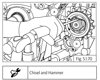
- Straighten lock tab washer (a) located over FD sprocket (b).

- Locate special tool over FD sprocket (a) and loosen hex "U" nut (M20) (b).

- Remove lock tab washer (a) from shaft.

- Remove FD sprocket (a) from drive shaft (b).

- Gently remove spacer (a) from drive shaft.

- Remove oil seal (a) from drive shaft.

See also:
 Royal Enfield Interceptor 650 - Service manual > Oil Level Window
Remove the circlip (a) on the oil level window inside clutch cover. Gently press oil window (a) from outer side to remove from clutch cover.
 Royal Enfield Interceptor 650 - Service manual > Reed Valves
Disconnect the hose (a) from the reed valve tube on the front side of cylinder head. Loosen and remove 4 Nos. Hex socket head screws (M6) (a) holding reed valves to cylinder head. Remove reed valve (a) from the cylinder head.
 Rider's Manual BMW R 1250 GS GSA
 Owner's Manual Harley-Davidson Sportster XL1200X Forty-Eight
 Owner's Manual Honda CBR650R
 Service manual Honda CBR650
 Owner's Manual Honda PCX125
 Owner's Manual Kawasaki Z1000SX
 Service manual Kawasaki Z1000SX
 Owner's Manual Lexmoto Echo
 Owner's Manual Royal Enfield Interceptor 650
 Service manual Royal Enfield Interceptor 650
 Owner's Manual Yamaha MT-07