 Kawasaki Z1000SX - Service manual > Drive Chain
Final Drive / Drive Chain
Drive Chain Slack Inspection
- Refer to the Drive Chain Slack Inspection in the Periodic Maintenance chapter.
Drive Chain Slack Adjustment
- Refer to the Drive Chain Slack Adjustment in the Periodic Maintenance chapter.
Wheel Alignment Inspection/Adjustment
- Refer to the Wheel Alignment Inspection in the Periodic Maintenance chapter.
Drive Chain Wear Inspection
- Refer to the Drive Chain Wear Inspection in the Periodic Maintenance chapter.
Drive Chain Lubrication
- Refer to the Drive Chain Lubrication Condition Inspection in the Periodic Maintenance chapter.
Drive Chain Removal
- Remove:
Mud Guard (see Mud Guard Removal in the Frame chapter)
Rear Wheel (see Rear Wheel Removal in the Wheels/Tires chapter)
Chain Cover Bolt [A]

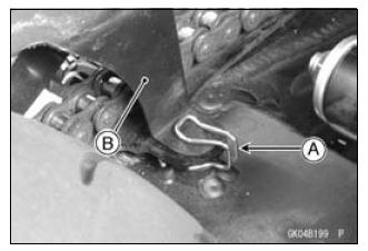
- Remove:
Clamp [A]
Chain Cover [B]
Swingarm (see Swingarm Removal in the Suspension chapter)

- Remove:
Engine Sprocket Cover (see Engine Sprocket Cover) - Remove the drive chain [A] from the engine sprocket [B], and take it off the chassis.

Drive Chain Installation
- Install the drive chain to the engine sprocket.
- Install:
Swingarm (see Swingarm Installation in the Suspension chapter)
Rear Wheel (see Rear Wheel Installation in the Wheels/Tires chapter)
Engine Sprocket Cover (see Engine Sprocket Cover Installation) - Insert the projection [A] on the chain cover into the swingarm hole [B].
- Adjust the drive chain slack after installing the chain (see Drive Chain Slack Adjustment in the Periodic Maintenance chapter).

Drive Chain Replacement
- Remove:
Chain Cover (see Drive Chain Removal)
Engine Sprocket Cover (see Engine Sprocket Removal)
NOTICE For safety, if the drive chain shall be replaced, replace it using a recommended tool.
Recommended Tool -
Type: EK Joint Tool #50
Brand: ENUMA
Body [A]
Handlebar [B]
Cutting and Riveting Pin [C]
For Cutting [D]
For Riveting [E]
Plate Holder (A) [F]
Plate Holder (B) [G]
Gauge [H]

- Grind [A] the pin head to make it flat.
- Set the cutting and riveting pin [B] as shown in the figure.

- Screw the pin holder until it touches chain pin.
- Be sure that the cutting pin hits center of chain pin.

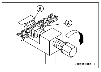
- Screw the handlebar [A] into body.
- Turn the pin holder with wrench [B] clockwise to extract chain pin.

- Replace the link pin, link plate and grease seals.
- Apply grease to the link pins [A] and grease seals [B] [C].
- Engage the drive chain on the engine and rear sprockets.
- Insert the link pins in the drive chain ends.
- Install the grease seals.
- Install the link plate [D] so that the mark faces out.
- Push the link plate by hand or plier to fix it.
- In case of grease seals chain, be sure to set the grease seals correctly

- Set the plate holder (A) [A] and plate holder (B) [B] on the body.

- Fit the plate holder (A) [A] to link plate.
- Turn the pin holder by hand until plate holder (B) [B] touches the other link plate.

- Turn the pin holder [A] by wrench clockwise until two pins of link come into groove of plate holders [B].
- Take off the plate holder.

- Set the plate holder (B) [A] and cutting and riveting pin [B] as shown in the figure.

- Turn the pin holder until riveting pin touches link pin.

- Turn the wrench clockwise until tip of riveting pin hits to the link pin.
- Rivet it.
- Same work for the other link pin.

- After staking, check the staked area of the link pin for cracks.
- Measure the outside diameter [A] of the link pin and link plates width [B].
Link Pin Outside Diameter
Standard: 5.6 - 6.0 mm (0.22 - 0.24 in.)
Link Plates Outside Width
Standard: 20.35 - 20.55 mm (0.8012 - 0.8091 in.)

If the reading exceeds the specified length, cut and rejoin the chain again.
- Check: Movement of the Rollers
- Adjust the drive chain slack after installing the chain (see Drive Chain Slack Adjustment in the Periodic Maintenance chapter).
See also:
 Kawasaki Z1000SX - Service manual > Final Drive
Exploded View
 Rider's Manual BMW R 1250 GS GSA
 Owner's Manual Harley-Davidson Sportster XL1200X Forty-Eight
 Owner's Manual Honda CBR650R
 Service manual Honda CBR650
 Owner's Manual Honda PCX125
 Owner's Manual Kawasaki Z1000SX
 Service manual Kawasaki Z1000SX
 Owner's Manual Lexmoto Echo
 Owner's Manual Royal Enfield Interceptor 650
 Service manual Royal Enfield Interceptor 650
 Owner's Manual Yamaha MT-07