 Royal Enfield Interceptor 650 - Service manual > Cylinder Head
Engine / Engine Inspection / Cylinder Head
Cylinder Head Inspection
- Inspect cylinder head carefully for any cracks, blow holes or damages - especially in the inlet and exhaust ports.
- Place thick straight edge across cylinder head gasket seating surface.
- Insert pointed feeler gauge of 0.01 mm thickness between straight edge and cylinder head.
- Inspect and ensure 4 locations (a, b, c, d) on cylinder head are at same level.

- Ensure feeler enters properly at marked places.

Rocker Cover to Cylinder Head Seating Surface
- Place the thick straight edge across the rocker cover gasket seating surface.
- Insert pointed feeler gauge of 0.01 mm thickness between straight edge and cylinder head at the marked places.

- Ensure feeler enters properly at marked places.

Rocker Cover
- Place thick straight edge across the rocker cover.
- Insert pointed feeler gauge of 0.01 mm thickness between straight edge and rocker cover.
- Inspect and ensure 4 locations (a, b, c, d) on rocker cover are at same level.

Rocker Arm
- Inspect rollers (a) for any wear and/or sticky rotation. Replace if defective.
- Measure the inner diameter (b) of the rocker arm.

Rocker Arm Shaft
- Check rocker arm shaft for pitting, score marks, uneven wear or damage. Replace if defective.
- Measure the diameter of the rocker shaft (a) at the rocker arm working area.

Tappet Adjusters
- Inspect "elephant foot" (a) for any wear and/or sticky rotation. Replace if defective.

Camshaft Run-out
- Inspect camshaft lobes for pitting, score marks, uneven wear or damage.
- Support the cam shaft on the 2 V-blocks (a).
- Rotate the camshaft slowly and measure run-out with a dial gauge (b) at the machined place.

Camshaft Journal OD
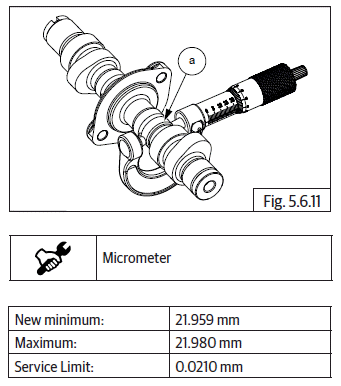
- Measure camshaft journal OD (a).

Camshaft Lobe
- Inspect cam lobes for scoring, wear-out and scratches.
- Measure height of each cam lobe (a).

Valve Inspection.
- Check each valve for wear, burn or distortion at its face and stem end. Replace valve, if necessary.
- Check valve stem end face for pitting and wear.
- When it is worn out, replace the valve.

Valve Guide ID (Inlet and Exhaust)
- Using micrometer and bore gauge, measure the ID of the valve guides at the top and bottom working area inside the guides.

Valve Spring (Inlet and Exhaust)
- Measure load on installed and working condition.

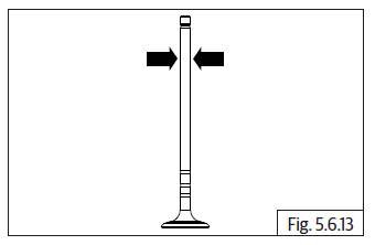
Valve Stem OD (Inlet and Exhaust Valve)
- Measure diameter at marked places along the length of each stem.

See also:
 Royal Enfield Interceptor 650 - Service manual > Cylinder Barrel
Cylinder Barrel Bore ID Check cylinder bore to piston working area for scoring, seizure marks and/or excessive wear. Measure the cylinder bore at the top, middle and bottom at the rings working area using a bore gauge. Measure at both across and along the gudgeon pin axis.
 Rider's Manual BMW R 1250 GS GSA
 Owner's Manual Harley-Davidson Sportster XL1200X Forty-Eight
 Owner's Manual Honda CBR650R
 Service manual Honda CBR650
 Owner's Manual Honda PCX125
 Owner's Manual Kawasaki Z1000SX
 Service manual Kawasaki Z1000SX
 Owner's Manual Lexmoto Echo
 Owner's Manual Royal Enfield Interceptor 650
 Service manual Royal Enfield Interceptor 650
 Owner's Manual Yamaha MT-07