 Royal Enfield Interceptor 650 - Service manual > Cylinder Barrel
Cylinder Barrel Bore ID
- Check cylinder bore to piston working area for scoring, seizure marks and/or excessive wear.
- Measure the cylinder bore at the top, middle and bottom at the rings working area using a bore gauge.
- Measure at both across and along the gudgeon pin axis.

Bore Taper Limit
- Measure the cylinder taper at three levels: Top (a), Middle (b), and Bottom (c) in the X and Y axis.

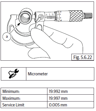
Piston OD
- Measure and record both LH and RH cylinder piston OD at three levels - Top, Middle, and Bottom using Micrometer.


Piston Pin Bore ID
- Measure both LH and RH cylinder piston pin bore (a) inner diameter using inside micrometer (b).


Piston Pin
- Measure the diameter of the piston pin (a).

Piston Ring End Gap
- Position the piston rings at their respective locations at the top of the cylinder barrel and ensure they are seated "squarely" inside the cylinder barrel.

- Measure piston rings end gap (a) using feeler gauge (b).

Crankcase
Connecting Rod Small End ID
- Measure the connecting rod small end inner diameter (a).

Connecting Rod Bend and Twist
- Support connecting rod suitably and firmly at the big end and measure bend/twist at the small end using a suitable scale.

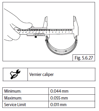
Connecting Rod Journal Bearing Clearance.
- Measure clearance between crankshaft journal connecting rod big end and bearings.

Balancer Shaft Run-out
- Place the balancer shaft in V-blocks.
- Rotate the balancer shaft and measure run-out with a dial gauge at the machined surface (a) and (b).

Balancer Shaft Face Out
- Place the balancer shaft in V-blocks.
- Rotate the balancer shaft and measure the web face out with a dial gauge at the specified place (a) and (b).

Balancer Shaft Journal Bearing Clearance
- Measure the clearance between balancer shaft journal and balancer shaft journal bearing.

Crankshaft Face Out
- Place the crankshaft on V-blocks.
- Rotate crankshaft and measure face out with a dial gauge at the specified place.

Crankshaft Run-out
- Place the crankshaft on V-blocks.
- Rotate the crankshaft and measure run-out with a dial gauge at the machined surface.

Crankshaft Journal Bearing Clearance
- Measure crankshaft journal to crankshaft journal bearing clearance.


See also:
 Royal Enfield Interceptor 650 - Service manual > Cylinder Head
Cylinder Head Inspection Inspect cylinder head carefully for any cracks, blow holes or damages - especially in the inlet and exhaust ports. Place thick straight edge across cylinder head gasket seating surface. Insert pointed feeler gauge of 0.01 mm thickness between straight edge and cylinder head. Inspect and ensure 4 locations (a, b, c, d) on cylinder head are at same level. Ensure feeler enters properly at marked places.
 Royal Enfield Interceptor 650 - Service manual > Clutch Components
Friction plate Inspect the clutch plates visually for uneven wear, seizure and discoloration. Measure the thickness of the friction plate (a) at 4 locations marked by arrows.
 Rider's Manual BMW R 1250 GS GSA
 Owner's Manual Harley-Davidson Sportster XL1200X Forty-Eight
 Owner's Manual Honda CBR650R
 Service manual Honda CBR650
 Owner's Manual Honda PCX125
 Owner's Manual Kawasaki Z1000SX
 Service manual Kawasaki Z1000SX
 Owner's Manual Lexmoto Echo
 Owner's Manual Royal Enfield Interceptor 650
 Service manual Royal Enfield Interceptor 650
 Owner's Manual Yamaha MT-07