 Kawasaki Z1000SX - Service manual > Exploded View, Exhaust System Identification
Exploded View
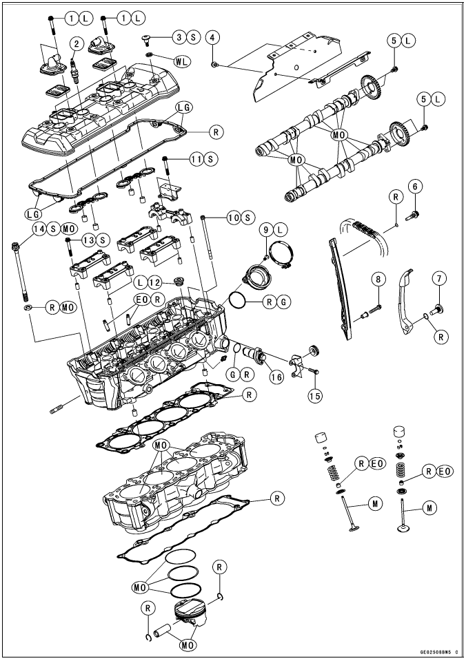

EO: Apply engine oil.
G: Apply grease.
L: Apply a non-permanent locking agent.
LG: Apply liquid gasket.
M: Apply molybdenum disulfide grease.
MO: Apply molybdenum disulfide oil solution.
(mixture of the engine oil and molybdenum disulfide grease in a weight ratio 10
: 1)
R: Replacement Parts
S: Follow the specified tightening sequence.
WL: Apply soap and water solution or rubber lubricant.


R: Replacement Parts
Exhaust System Identification

Exhaust Pipe Mark Position [A]

Left Muffler Body Mark Position [A]

Right Muffler Body Mark Position [A]

Exhaust Pipe [A] with Hole [B] for Oxygen Sensor [C] (Equipped Models)

Honeycomb Type Catalyst Positions [A]

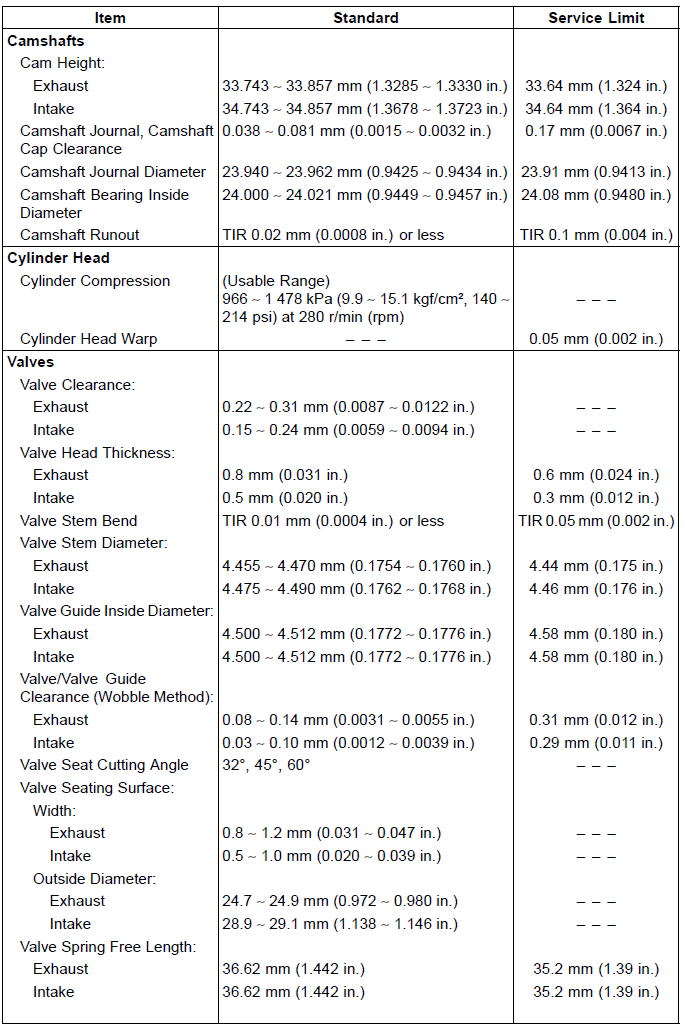
Specifications

Special Tools and Sealant
Compression Gauge, 20 kgf/cm²: 57001-221

Valve Seat Cutter, 32º -  28:
57001-1119

Valve Spring Compressor Assembly: 57001-241

Valve Seat Cutter Holder Bar: 57001-1128

Piston Pin Puller Assembly: 57001-910

Valve Seat Cutter, 32º -  33:
57001-1199

Valve Seat Cutter, 45º -  27.5:
57001-1114

Valve Seat Cutter Holder,  4.5:
57001-1330

Valve Seat Cutter, 45º -  32:
57001-1115

Valve Guide Arbor,  4.5:
57001-1331

Valve Guide Reamer,  4.5:
57001-1333

Valve Spring Compressor Adapter,
 24: 57001-1586
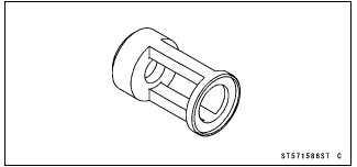
Valve Seat Cutter, 60º -  33:
57001-1334

Compression Gauge Adapter, M10 × 1.0: 57001-1601

Valve Seat Cutter, 60º -  27:
57001-1409

L-Shape Hose: 57001-1606

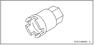
Engine Mount Nut Wrench: 57001-1450
Washer: 57001-1612

Valve Guide Driver: 57001-1564

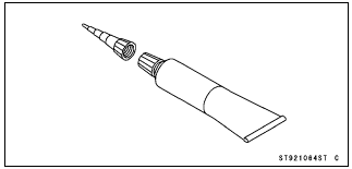
Liquid Gasket, TB1216B: 92104-1064
See also:
 Kawasaki Z1000SX - Service manual > Clean Air System
Air Suction Valve Removal Remove: Lower Fairing (see Lower Fairing Removal in the Frame chapter) Air Switching Valve (see Air Switching Valve Removal) Stick Coil Connector (see Stick Coil Removal in the Electrical System chapter) Connector [A] (from Bracket [B] at Left Side) Air Suction Valve Cover Bolts [C] and Bracket Air Suction Valve Covers [D] (Both Sides) Remove the air suction valves [A] on both sides.
 Rider's Manual BMW R 1250 GS GSA
 Owner's Manual Harley-Davidson Sportster XL1200X Forty-Eight
 Owner's Manual Honda CBR650R
 Service manual Honda CBR650
 Owner's Manual Honda PCX125
 Owner's Manual Kawasaki Z1000SX
 Service manual Kawasaki Z1000SX
 Owner's Manual Lexmoto Echo
 Owner's Manual Royal Enfield Interceptor 650
 Service manual Royal Enfield Interceptor 650
 Owner's Manual Yamaha MT-07