 Honda CBR650 - Service manual > Clutch
REMOVAL
Remove the right crankcase cover.
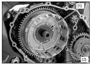
Remove the thrust washer [1] and wave washer [2] from the starter idle gear.

Remove the starter idle gear [1] and shaft [2].

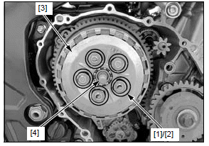
Remove the clutch spring bolts [1], springs [2] in a crisscross pattern in two to three steps, then remove the pressure plate [3].
Remove the clutch lifter piece [4] from the lifter bearing.

Remove the following:
- Clutch disc A [1]
- Five clutch discs [2]
- Six clutch plates [3]
- Clutch disc B [4]
- Judder spring [5]
- Spring seat [6]

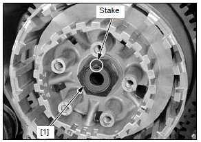
Unstake the clutch center lock nut [1].

Hold the clutch center [1] with the special tool and remove the clutch center lock nut [2].
TOOL:
[3] Clutch center holder 07724-0050002 or equivalent commercially available
Discard the lock nut.

Remove the lock washer [1], thrust washer [2] and clutch center [3].

Remove the thrust washer [1] and clutch outer [2].

Remove the needle bearing [1].

Remove the bolt [1] and oil pump drive chain guide [2].

Remove the oil pump driven sprocket washer-bolt [1].
Remove the oil pump drive sprocket [2], driven sprocket [3] and drive chain [4] as an assembly.

Remove the clutch outer guide [1].

INSPECTION
Inspect the following parts for scratch, damage, abnormal wear and deformation.
- Clutch lifter bearing
- Clutch lifter plate
- Clutch springs
- Clutch center
- Spring seat
- Judder spring
- Clutch discs/plates
- Clutch outer/primary driven gear/needle bearing
- Clutch outer guide
- Oil pump drive/driven sprocket
- Oil pump drive chain
- Mainshaft
Measure each part according to CLUTCH/GEARSHIFT LINKAGE/STARTER CLUTCH SPECIFICATIONS.
Replace any if it is out of service limit.
- Replace the clutch springs as a set.
- Replace the clutch discs and plates as a set.
INSTALLATION
Apply molybdenum oil solution to the clutch outer guide [1] sliding surface and install it to the mainshaft.

Apply oil to the oil pump drive sprocket [1] and driven sprocket [2] teeth.
Install the oil pump driven sprocket with its "OUT" mark [3] facing out.
Install the oil pump drive/driven sprocket and drive chain [4] as an assembly.
Apply a locking agent to the oil pump driven sprocket washer-bolt [5] threads.
Be careful not to drop the parts into the oil pan.
Install the oil pump driven sprocket bolt with the washer [6] and tighten the bolt to the specified torque.
TORQUE:15 N*m (1.5 kgf*m, 11 lbf*ft)

Be careful not to drop the parts into the oil pan.
Install the oil pump drive chain guide [1] by aligning the hole with boss of crankcase.
Tighten the bolt [2] securely.

Apply engine oil to the rotating area of the needle bearing [1].
Install the needle bearing onto the mainshaft.

Apply molybdenum oil solution to the clutch outer [1] gear and sliding surface.
Install the clutch outer by aligning the holes with the tabs of the oil pump drive sprocket.

Install the thrust washer [1].

Install the clutch center [1] and thrust washer [2].
Install the lock washer [3] with its "OUT" mark [4] facing out.

Apply engine oil to the threads and seating surface of a new clutch center lock nut [1], then install it onto the mainshaft.
Hold the clutch center [2] with the special tool and tighten the lock nut to the specified torque.
TOOL:
[3] Clutch center holder 07724-0050002 or equivalent commercially available
TORQUE:128 N*m (13.1 kgf*m, 94 lbf*ft)

Be careful not to damage the mainshaft threads.
Stake the lock nut [1] into the mainshaft groove with a punch.

Install the spring seat [1] and judder spring [2] onto the clutch center as shown.

Coat the clutch discs and plates with clean engine oil.
NOTE:
- Clutch disc A [1]: Identification mark [2] on a tab
- Clutch discs [3]: No mark
- Clutch disc B [4]: Large I.D.
Install the clutch disc B into the clutch outer.
Stack the five clutch discs, six plates [5] and clutch disc A alternately.
Install the clutch disc A by aligning the tab with the shallow slots [6] of the clutch outer.

Install the lifter bearing [1] into the pressure plate.
Install the clutch lifter piece [2] into the lifter bearing.

Install the pressure plate [1].
Install the clutch springs [2] and spring bolts [3].
Tighten the bolts to the specified torque in a crisscross pattern in two to three steps.
TORQUE:12 N*m (1.2 kgf*m, 9 lbf*ft)

Apply molybdenum oil solution to the starter idle gear shaft [1] outer surface.
Install the starter idle gear [2] and shaft.

Install the wave washer [1] and thrust washer [2] onto the starter idle gear.
Install the right crankcase cover.

See also:
 Honda CBR650 - Service manual > Service information
GENERAL This section covers service of the clutch, gearshift linkage and starter clutch. All service can be done with the engine installed in the frame. Engine oil viscosity and level have an effect on clutch disengagement. When the clutch does not disengage or the motorcycle creeps with clutch disengaged, inspect the engine oil level before servicing the clutch system. For starter motor service.
 Honda CBR650 - Service manual > Starter clutch
REMOVAL Remove the clutch. Remove the starter reduction gear [1] from the crankcase.
 Rider's Manual BMW R 1250 GS GSA
 Owner's Manual Harley-Davidson Sportster XL1200X Forty-Eight
 Owner's Manual Honda CBR650R
 Service manual Honda CBR650
 Owner's Manual Honda PCX125
 Owner's Manual Kawasaki Z1000SX
 Service manual Kawasaki Z1000SX
 Owner's Manual Lexmoto Echo
 Owner's Manual Royal Enfield Interceptor 650
 Service manual Royal Enfield Interceptor 650
 Owner's Manual Yamaha MT-07